
3D Sensing Technology Built for Real-World Integration

From optical simulation and hardware design to 3D calibration, depth processing and application algorithms, X-dynamics develops the core technologies behind reliable iToF and dToF sensing solutions.

Explore Our Technology Download Resources
Two ToF Technology

Different applications require different forms of depth and distance information.
X-dynamics develops both iToF 3D cameras for spatial depth perception and dToF modules for compact, long-range distance measurement.
This dual-technology portfolio enables customers to select the sensing architecture that best matches their range, resolution, field of view, environmental and integration requirements.
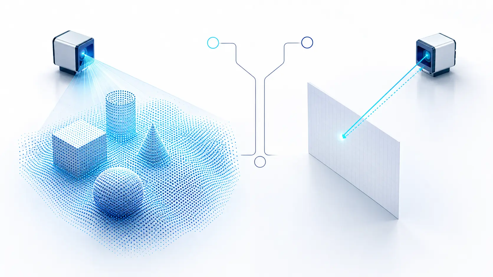

iToF 3D Imaging
dToF Laser Ranging

Core Technologies

Optical Design

Self-developed optical design and simulation support the development of high-precision 3D sensing systems.

Hardware Design

In-house hardware design supporting the development of X-dynamics 3D sensing products.

3D Calibration

Self-developed 3D calibration technology establishes accurate spatial relationships between sensor data and real-world coordinates.

Calibration Algorithms

Self-developed calibration, data-acquisition and correction algorithms improve depth accuracy and measurement consistency.

ISP & Point Cloud Processing

ISP, filtering, denoising and flying-point removal algorithms improve depth-image and point-cloud quality.

AI Application Algorithms

Application algorithms support people counting, pallet recognition, obstacle detection, volume measurement and industrial safety monitoring.

From Optical Sensing to Actionable 3D Data

A reliable 3D sensing system requires more than a sensor. Optical, electronic and algorithmic components must work together throughout the complete data pipeline.

Light Emission

Controlled infrared or laser light is emitted into the target environment for stable and reliable three-dimensional sensing.

Signal Capture

Reflected light is captured and converted into raw sensing signals for subsequent depth calculation and data processing.

Depth Calculation

Calibration, correction and depth algorithms convert raw optical signals into reliable distance and depth information.

Data Processing

Filtering, denoising, interference suppression and point-cloud generation improve depth quality, stability and data reliability.


Application

Processed depth, point-cloud and event data are delivered to customer software, robots and industrial systems through interfaces.

Download Resources

FAQ

Frequently Asked Questions

Find answers to common questions about X-Dynamics 3D ToF cameras, imaging performance, installation, PC software, SDK integration and hardware customization.

RGB availability depends on the product model and configuration. X-Dynamics offers both depth-only and RGB-D versions. RGB-enabled models support synchronized RGB-D data and RGB with point cloud visualization. Please confirm the required configuration before ordering.

Make sure there are no objects blocking the camera lens or field of view. For desktop testing, do not position the camera where the desktop blocks the lower part of the viewing area. Keep the optical window level with the edge of the mounting surface and follow the installation requirements for the specific model.

X-Dynamics ToF cameras use active infrared illumination, typically in the 850 nm or 940 nm wavelength range. External light sources operating in the same range may cause interference. Our optical design and software algorithms help reduce strong-light interference, with selected models supporting operation under ambient illumination of up to 100,000 lux.

Yes. iToF cameras actively emit infrared light and calculate distance from the returned signal, so they do not rely on visible texture or color features. However, very dark or low-reflectivity surfaces may return less energy and affect measurement performance.

Highly reflective materials located close to the camera may cause overexposure, multipath reflections or unstable depth values. Reflective objects farther away can generally be measured when they remain within the supported operating range.

Transparent glass is difficult to measure reliably because it can transmit or specularly reflect infrared light. Measurement performance depends on the material’s transparency and surface characteristics. Less transparent materials generally provide more stable depth data. Where required, filtering algorithms can be used to reduce interference from glass surfaces.

Corners may cause multipath interference. Instead of returning directly to the camera, emitted infrared light can reflect several times between nearby surfaces. This increases the measured travel time and may produce inaccurate or unstable depth values around corners.

Yes. Multiple X-Dynamics cameras can operate in the same environment. Because iToF cameras may use similar modulation frequencies, mutual interference can occur without suitable configuration. X-Dynamics provides multi-camera interference suppression algorithms, with supported configurations accommodating up to 10 devices.

The software may be blocked by Windows Firewall or antivirus software, or the required Windows runtime components may be missing. Add the software to the security allowlist, reinstall it if necessary, and make sure Microsoft .NET Framework 4.7.1 and the Microsoft Visual C++ 2015 Redistributable are installed.

First, confirm that the camera is powered correctly and that its indicator light is on. Then check the Ethernet or USB connection. For Ethernet models, make sure the camera and computer are on the same network segment, verify the connection using the ping command, and confirm that the IP address entered in the software matches the camera’s IP address.

Set the computer’s IP address to the same network segment as the camera without using the camera’s exact IP address. Open the Windows command prompt and run the ping command followed by the camera IP address. A successful reply indicates that network communication is working normally.

Check the power supply, network cable and communication status, then restart the software. The current PC software supports Windows 10 and Windows 11. If the issue continues, power off the camera, restart it and reconnect the device.

The exposure or integration time may be too short, resulting in insufficient returned infrared energy. If it is too long, the image may become overexposed. Adjust the exposure time in Parameter Settings according to the required measurement range. Also check the confidence and filtering settings, as higher filtering levels may remove weak depth signals.

Use the Horizontal Mirror and Vertical Mirror options in the X-Dynamics PC software. These settings allow the displayed image orientation to match the camera’s actual mounting direction.

Large red areas usually indicate abnormal depth values caused by interference, overexposure or incorrect installation. Remove any protective film from the optical window and make sure the camera is not placed behind an obstructing surface. For X-D500 desktop testing, keep the camera at least 15 cm above the surface and align its optical window with the edge of the mounting area.

Depending on the product model, the X-Dynamics PC software and SDK can output depth data, point cloud data, grayscale data, confidence data and RGB data. RGB data is available only on RGB-enabled models.

Captured frames are stored sequentially in their original format without intermediate padding or compression. The raw data size of each frame can be calculated as width × height × bytes per pixel. Point cloud data can be exported in PLY format and viewed using compatible software such as CloudCompare.

A return value of 0 indicates that the camera was opened successfully. A return value of -3 indicates a camera connection timeout. Check the power supply, physical connection, network configuration, camera IP address and SDK device settings.

Configure the device model and IP address in the CreateStreamerNet() interface. Then configure OpenCamera() according to whether the camera is depth-only or equipped with RGB. Additional parameters, including exposure, frame rate and filtering settings, should be configured according to the camera model and application requirements.

Yes. X-Dynamics provides OEM and ODM customization services. The module dimensions, structure and integration method can be evaluated and adjusted according to your product design and the technical requirements of the camera.

Yes. Standard physical interfaces and communication protocols can often be supported by modifying the connection cable or adapter board. Special interface requirements must be evaluated together with the camera structure, electrical design and application requirements.

The X-D500 three-in-one cable includes a DC5521 male connector for 24 V power input, a 2-pin terminal for CAN communication and an RJ45 connector for 100 Mbps Ethernet communication.

Image instability may be caused by insufficient power, loose power or network connections, or vibration at the installation location. For the X-D500, a 24 V/3 A power adapter is recommended, especially when using longer integration times or higher frame rates. Secure all connectors and make sure the camera is mounted on a stable, vibration-free structure.

Ready to Start Your Own Project​?


Get in Touch with XDynamics

Project Inquiry

Tell us your application, technical requirements, or project needs. Our team will recommend suitable products and integration options.

Address

6F, Building C2, Wuhan Future Science and Technology City, No.999 Gaoxin Blvd, Wuhan, Hubei 430205, China.